
Home > Kit Assembly Guides
Kit Assembly Guides
Core Kit Assembly Guide

This guide provides you with diagrams of the high level steps to assemble the single coil and humbucker guitar core.
Step 1
Assemble the pickup sub-assembly as shown below.
Note: The 2 screws can be adjusted at the end of the assembly process to set the height of the pickups relative to the strings.

Step 2
Position the bridge ground wire (with pre-soldered contact) as shown below. The bridge will clamp down on the wire when fastened to the core, grounding the bridge.
Tip: You can use a piece of tape (shown in blue) to hold the wire in place. The metal contact should be routed in the direction of the red arrow.

Step 3
Single Coil - Mount the pickup assembly to the core using QNTY 4 screws (#4 x 3/8”). Route the wires following the red arrows shown below.
Humbucker - Mount the bridge to the core using QNTY 3 shorter screws (#4 x 3/8”) and QNTY 2 longer screws (#4 x 1”).
Note: Make sure the bridge is clamping down on the exposed end of the ground wire from the previous step.

Step 4
Single Coil - Mount the bridge pickup assembly to the core using QNTY 3 shorter screws (#4 x 3/8”) and QNTY 2 longer screws (#4 x 1”).
Note: Make sure the bridge is clamping down on the exposed end of the ground wire from the previous step.
Humbucker - Mount the 2x pickup assemblies to the core using QNTY 8 screws (#4 x 3/8”) .
Note: Mount the neck pickup first (route the red wire and contacts as shown below), then repeat for the bridge pickup (green wire).

Step 5
Assemble the latch / contacts sub assembly.
Mount the latch handle cover top and bottom using QNTY 1 screw (#4 x 3/8”).
Mount the latch to the contacts adapter using QNTY 2 screws (#8 x 7/16”).
Note: You may need to move the latch out of the way to get access to fasten these screws.

Step 6
Slide the wire contacts onto the contacts adapter sub-assembly using the wire diagrams below.
Note: The diagram below is a Bottom View as shown

Step 7
Fasten the contacts adapter sub-assembly to the core using QNTY 4 screws (#6 x 3/4”).
Note: Wires not shown in diagrams below.
Note: Dual Humbucker Shown Below. Step is the same for Single Coil.
Caution: Make sure not to pinch the wires.

Step 8
Mount the neck to the core using the neck plate and QNTY 4 long neck screws (#8 x 1-1/2”).
Note: Dual Humbucker Shown Below. Step is the same for Single Coil.

Step 9
String and setup!

Body Kit Assembly Guide

This guide provides you with diagrams of the high level steps to assemble a guitar body.
Note: The diagrams below use the Strat River design as an example. Your guitar body may be different, but the same general steps apply.
Step 1
Glue the 3D printed parts together:
Apply glue in dowel holes and insert dowels
Apply glue to mating faces (shown in blue below) as well as exposed dowels
Press parts together
Important: Apply pressure and hold parts securely for proper bonding.
Tip: You can use wood clamps to assist.

Step 1b (Optional, but Recommended)
To ensure the body “tracks” are straight and parallel, use the optional (but recommended) body alignment jig. Slide the jig into the tracks while the glue is still setting and remove it once the body components are fully bonded.
Tip: Ensure the tracks are free and clear of any potential CA glue that may have seeped to ensure the alignment jig does not bond to the guitar body.

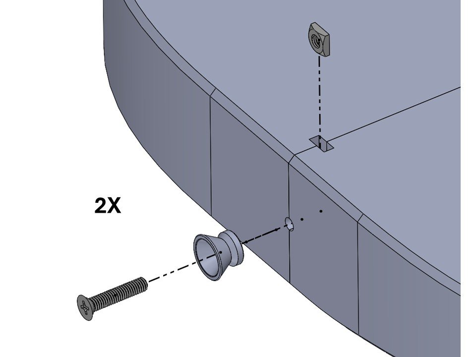
Step 2
After glue has fully set, flip body over and insert 2x square nuts (M4) into the slots. Then fasten 2x strap posts to the body using 2 screws (M4x20).
Tip: Ensure slot is free of any support material to ensure square nut will fully insert.
Step 3
Flip body back over. Route the controls harness wires as shown in the cross section below.
Red Arrows - Route the 5x contact wires through the slot to the contacts adapter mount area as shown.
Blue Arrow - Route the output jack through as shown.


Step 4
Connect the output jack cover to the output jack as shown below.

Step 5
Mount the output jack sub-assembly to the body using 4x screws (#2 x 3/8”).

Step 6
Fix the electronic controls to the body using 2x screws (#4 x 3/8”).

Step 7
Mount the latch hook to the body contacts adapter using 2x screws (#8 x 7/16”).

Step 8
Slide the wire contacts onto the body contacts adapter sub-assembly using the wire diagram below.
Note: The diagram below is a Bottom View as shown

Step 9
Fasten the contacts adapter sub-assembly to the core using QNTY 4 screws (#6 x 3/4”).
Note: Wires not shown in diagrams below.
Caution: Make sure not to pinch the wires.

Step 10
Finished!

Resin Pour Guide (Optional)

This guide provides you with the high level steps to pour a resin top for your guitar body.
Note: All of the “River” bodies have a recess that is specifically designed for a resin pour, but you can incorporate resin into any of the body designs
Step 1
Seal the seams between the body sections with super glue to ensure the resin does not seep when poured.
Important: Allow time for the super glue to fully set before moving to the follow steps

Step 2
Use a level to ensure your work surface is completely flat so that resin cures evenly.
Important: Check for level-ness in all directions

Step 3
Mixing the resin. You can use any resin you choose, but I recommend JB Weld UltraRez (affiliate link) because it cures without a tint and is rock-solid.
Resin Volumes: Use the table provided below for approximate resin volumes to use:


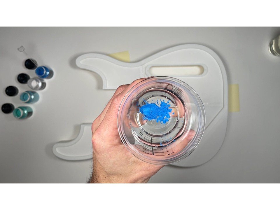
Step 4 (Optional, but Recommended)
Add mica powder coloring. Mix colors to get your perfect blend! I recommend this mica powder (affiliate link), because it is very affordable and comes with a great pallet of colors!
Note: A small scoop goes a long way!
Recommendation: Add the mica powder to the Part A resin, then add Part B afterwards and mix thouroughly.


Step 5
Carefully pour the resin mixture into the body recess.

Step 6 (Optional)
Use a pointed stick to create a “swirl” pattern in the resin.
Recommendation: Perform this step multiple times as needed as the resin sets to ensure the swirl pattern will remain

Step 7
Allow a full 24 hours for the resin to fully cure/set. Done!

✅ Questions?
Use the Contact Form to get in touch!